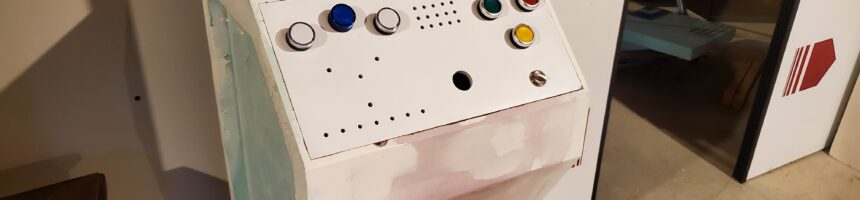
There was one question everyone asked when they learned I was building a science-fiction airlock:
“Will it make the pssshhh sound?”
Everyone asked.
It did not matter that the door had unusual geometry, custom graphics, glowing arc reactors, a control panel or an actual mechanism capable of moving two heavy pocket doors. Apparently, none of those things officially makes something an airlock.
It has to make the pssshhh sound.
I briefly considered producing the sound honestly. An air cylinder would have provided both the motion and the satisfying discharge of compressed air. It also would have required an air compressor, an expensive cylinder and a level of mechanical complexity that seemed excessive (even for me).
So I did what any sensible (?) builder would do.
I faked it.
That decision led to a sound-effects system. The sound system needed electronic controls. The controls became part of a larger control panel. The panel eventually controlled a motor. The motor required power electronics and limit switches. Those systems required more wiring, more software and, ultimately, three Arduino Megas.
All because everyone wanted the pssshhh sound.
Building the Control Panel
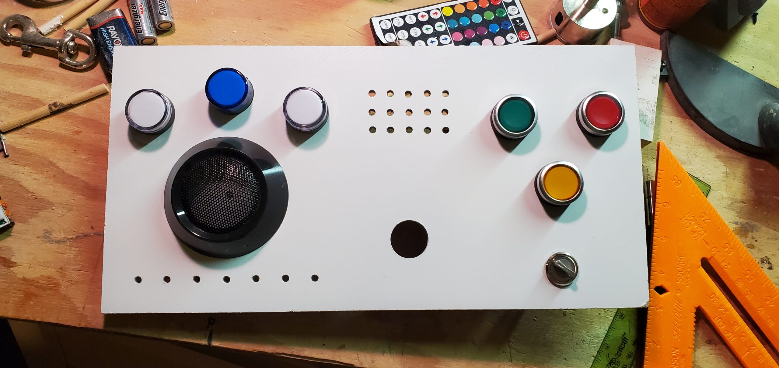
I introduced the finished control panel in Part 2, but the panel began as a simple sheet of 1/8-inch hardboard.
The surrounding facade was made from insulating foam, which was excellent for producing large shapes but not ideal for supporting buttons. The green and red door controls have a satisfyingly solid click. Repeatedly pushing them into unsupported foam would eventually damage the facade.
The hardboard provided a rigid mounting surface for the switches, lights and other components.
Of course, installing a rectangle of hardboard inside a foam structure presented a cosmetic problem. I did not want the panel to look like a separate board attached to the front of the facade. It needed to look like one continuous component.
I filled and shaped the surrounding area, sanded the transitions and integrated the hardboard into the foam housing. The complete assembly was eventually coated with StyroSpray 1000, which helped unify the materials and eliminate the visible seams.
We will talk more about that coating process in the next post.
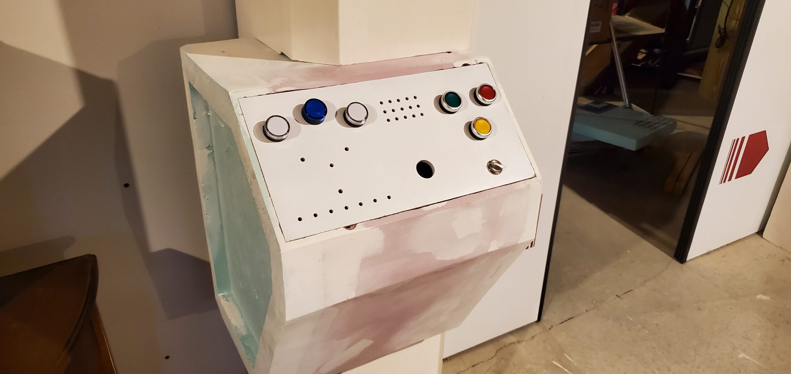
The panel can also be removed using the wooden toggles described in Part 6. That service access became rather important once the number of wires behind it began multiplying.
The Blinking Lights Department
The control panel contains several groups of lights. Some provide information. Others exist because blinking lights belong on control panels.
Across the upper left are three large indicators: white, blue and white. The active light slowly bounces back and forth between them.
Below those is the long rectangular display with seven small windows. This is the obligatory Larson scanner: a light traveling from side to side in the style of Knight Rider and Battlestar Galactica.
The Larson scanner was one of the things that originally inspired me to become an electrical engineer. Apparently, I chose an entire profession because I wanted to make lights bounce back and forth.
I regret nothing.
All the lights in these displays are individual LEDs. I could have reduced the number of control lines using charlieplexing or some other clever arrangement, but I was not interested in clever. Clever would complicate both the hardware and software.
Instead, I selected an Arduino Mega because it has a gloriously excessive number of digital input/output pins.

The 3×5 display near the top center provides three different kinds of almost-useful information:
- The top row is completely random.
- The middle row animates from the outside inward in Mode A and from the inside outward in Mode B.
- The bottom row displays the current threat level.
The threat level counts from zero to five. Zero means no threat. Five means something has gone terribly wrong – or at least that ten-second intervals have passed several times.
In reality, it would make more sense for the threat level to increase every few minutes. Unfortunately, no one wants to stare at a prop for half an hour waiting for the next light to turn on. The current interval is about ten seconds.
Sometimes realism must yield to the human attention span.
Two Modes, Two Buttons and One Klaxon
The green and red illuminated controls are both lights and tactile push buttons.
The green button opens the door. The red button closes it. I guess that sort of translates to – open = good and closed = danger?
A small toggle switch selects between two operating modes:
- In Mode A, pressing a button once commands the door to travel fully open or fully closed.
- In Mode B, the door moves only while the corresponding button is held. Release the button and the door stops.
The yellow illuminated button controls the alert system. When an alert is active, the light flashes and the system can produce a Star Trek-inspired klaxon. If there is no alert pending, pressing the button results in the reassuring announcement, “All systems nominal.”
The large circular control contains another blue LED. A motion sensor briefly illuminates it whenever someone approaches.
The motion sensor does not open the doors. It is a cheap sensor and not particularly reliable. More importantly, automatically opening the doors whenever someone walked past would make the airlock feel less like a spacecraft and more like the entrance to a grocery store.
Finally, a lighted power switch beneath the panel turns the overall system on and off.
Adding the Sound
The Arduino Mega could handle the LEDs, switches and basic control logic, but I used a separate Adafruit Audio FX Mini Sound Board for the sound effects.
The board stores the audio files locally. Its playback behavior is determined partly by the filenames assigned to those files, and individual inputs can be triggered by the Arduino. This provided a compact way to play several effects without making the Mega process audio itself.
The sound library includes:
- A looping mechanical sound while the doors are moving
- The required pssshhh when the doors stop
- A klaxon
- The “All systems nominal” announcement
- An error sound
Getting the correct sound to start, loop, stop and transition into the next sound without an awkward delay required some experimentation. The concept was simple; making it feel responsive took more work.
The version of the sound board I purchased did not include an audio jack, so I added one. A standard stereo cable connects the board to an independently powered amplifier. The amplifier and speakers are hidden above the doors inside the upper bulkhead.
The bulkhead became a convenient home for more than audio equipment. It also hides the wiring, amplifier, speakers, a power outlet and a small power-distribution strip.
Science-fiction architecture is apparently subject to the same rule as ordinary architecture: eventually, everything becomes a place to hide wires.
The Brains of the Operation
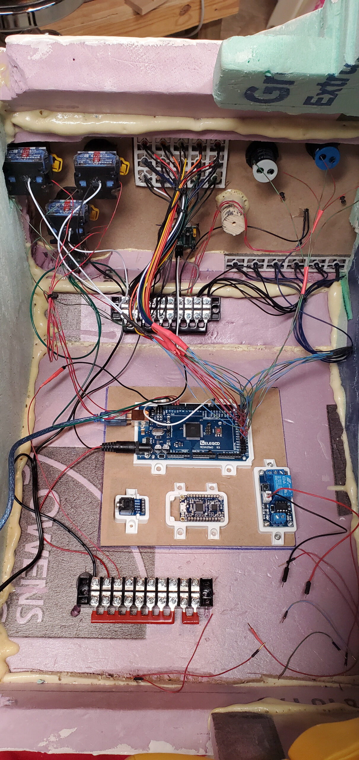
The main control system is built around the Arduino Mega and powered by a 5-volt supply.
The wiring photograph shows most of the electronic components used in the build. There are terminal blocks, relays, LED connections, button wiring, sensor inputs, the audio board and a distressing number of individual conductors.
I did not construct a sophisticated wiring harness between the removable facade sections. Fortunately, the distribution was relatively simple:
- The right pillar primarily needs power for the arc reactors and flux capacitor.
- The overhead section needs power for its LEDs and independently powered audio equipment.
- Most of the control electronics live near the control panel.
I went through three Arduino Megas during the project.
I do not remember what happened to the first one. The second one met a more memorable end when I connected a relay breakout board incorrectly. The board arrived without a useful wiring diagram, I guessed wrong, and the Mega paid the price.
The third Arduino has enjoyed the benefit of the lessons learned from its predecessors.
The Arc Reactor Mk. 1
The first arc reactor was inspired by the original unit Tony Stark built in Iron Man. Its construction combined 3D printing, repurposed materials and a surprising amount of hand-wound copper wire.
Most of the central metallic-looking components were 3D printed (and then painted). The perforated center grille was cut from a stainless-steel remnant salvaged from an old dishwasher.
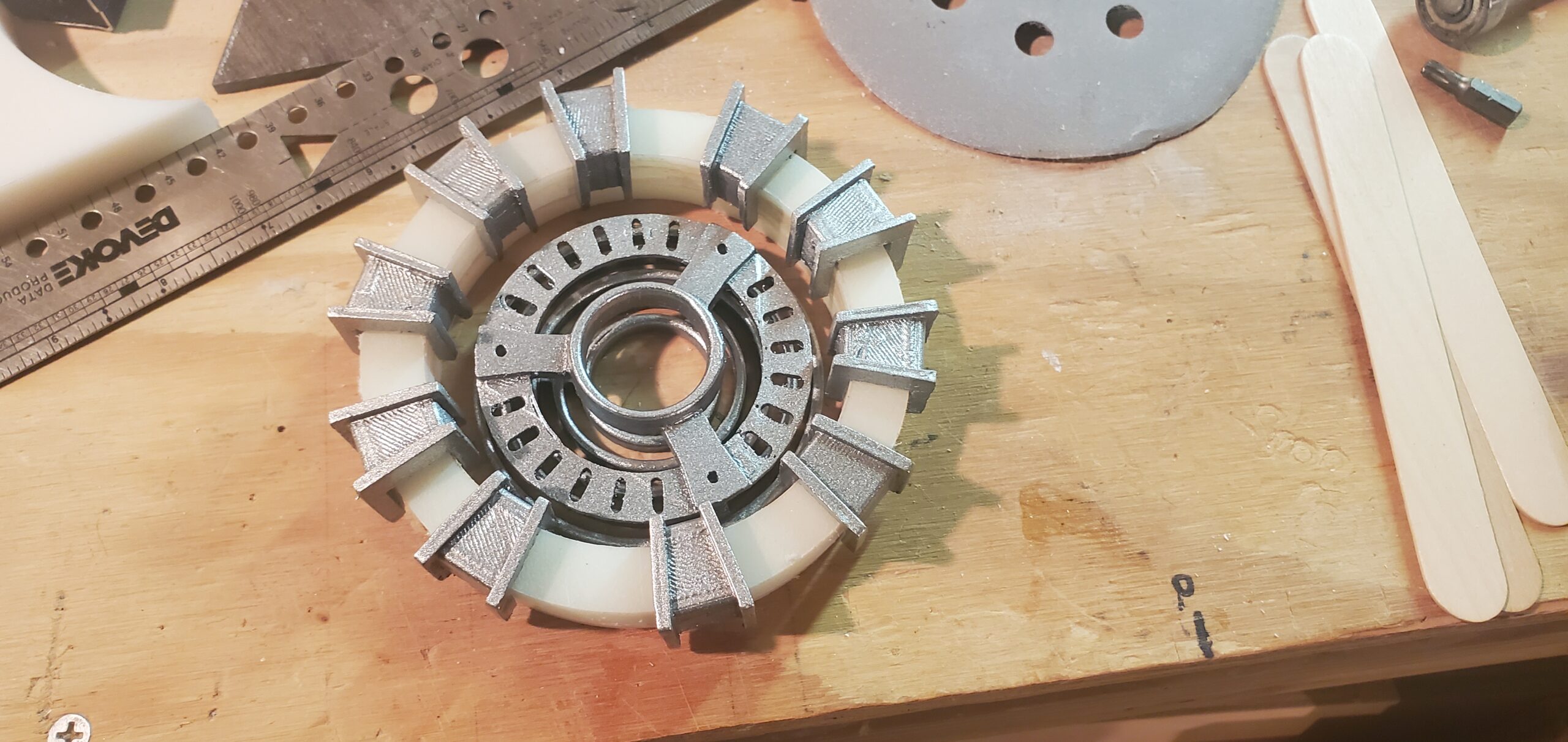
The white outer ring came from an old commercial cutting board. Small 3D-printed forms were arranged around the ring to support the decorative copper coils.
Then I wound them.
Carefully.
By hand.
The copper windings are completely nonfunctional, but they are also one of the details that gives the reactor its distinctive appearance. Sometimes a prop requires a great deal of real work to create something that only appears to do work.
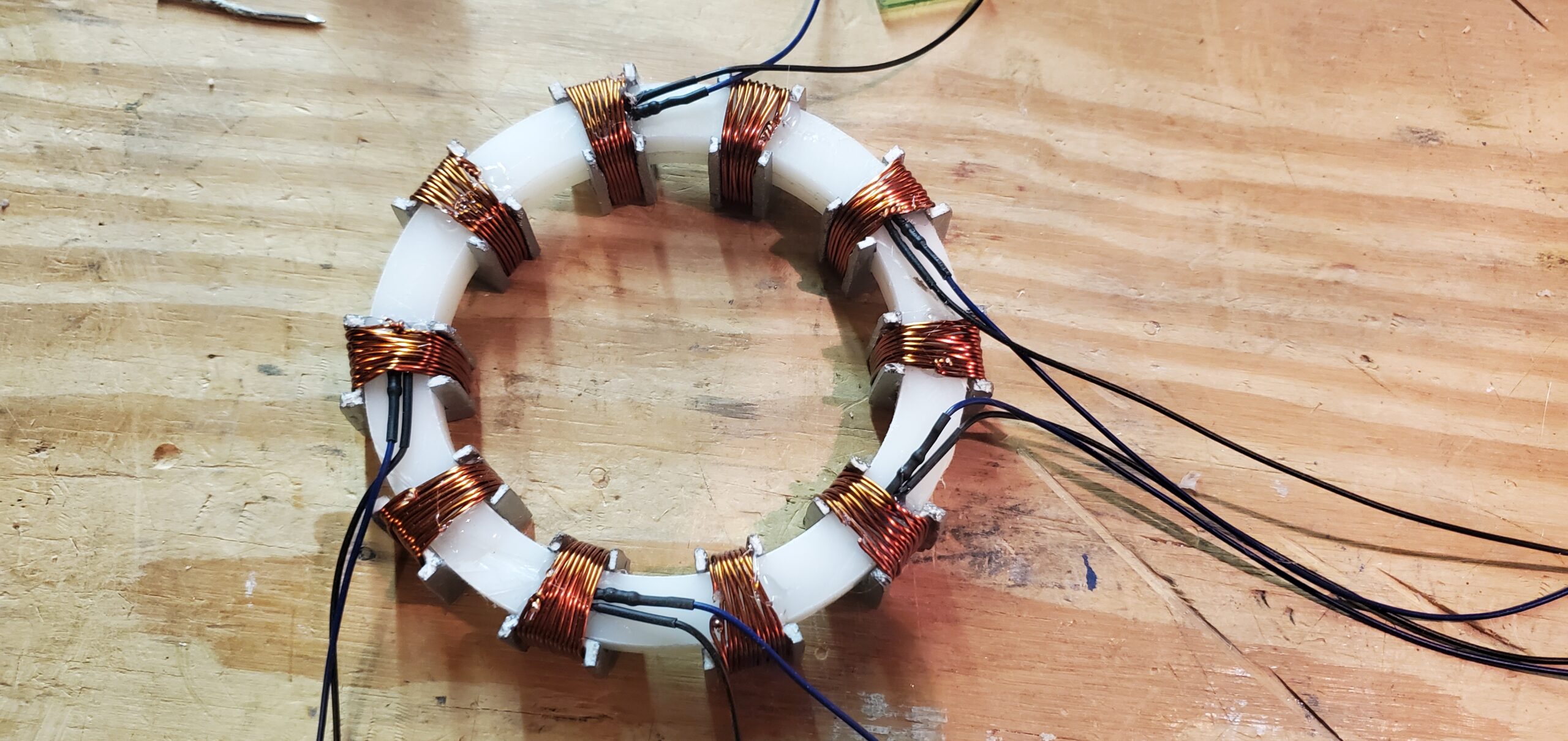
Individual blue LEDs provide the illumination. The white cutting-board material diffuses their light around the ring, and the reactor remains steadily illuminated whenever the airlock is powered.
The Other Arc Reactor
The Mk. 3 reactor was a much faster build because nearly the entire structure was 3D printed.
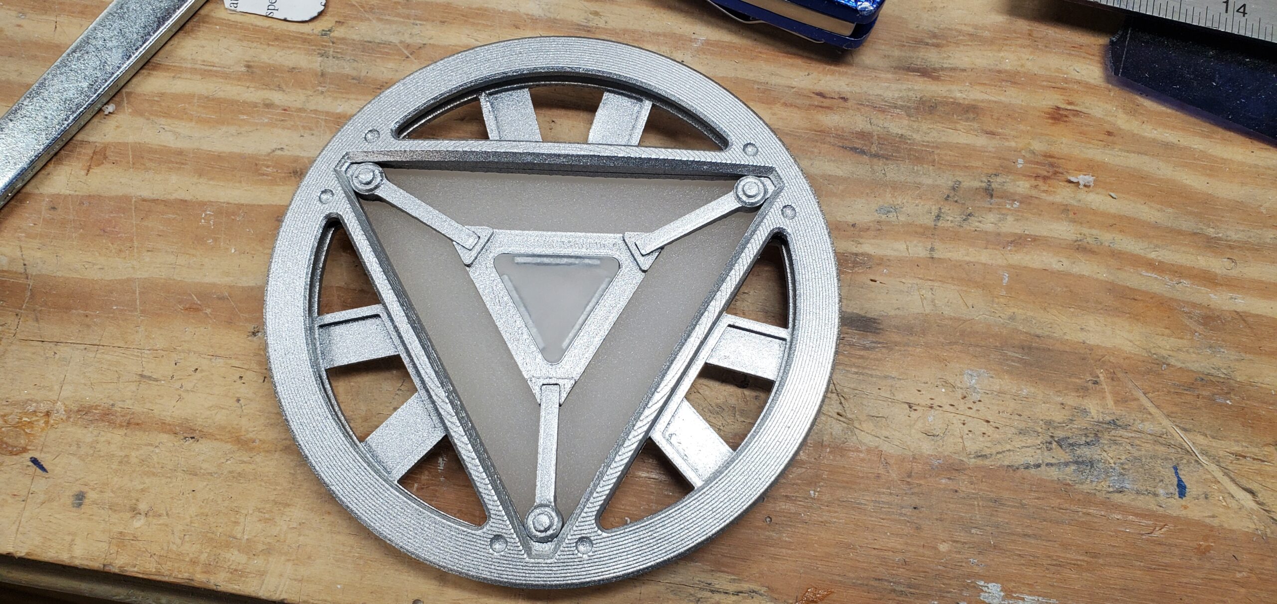
The transparent sections were made from pieces of plexiglass. I sanded their surfaces to diffuse the light and illuminated them with blue-green LEDs. Like the Mk. 1, this reactor remains steadily lit.
It is probably wise for a spacecraft to have redundant power sources.
Even if both of them are plugged into the wall.
The Flux Capacitor
The flux capacitor began as an emergency repair.
As described in Part 2, I dropped a ladder and gouged the nearly completed facade. My wife suggested that the damaged area needed lasers. A flux capacitor containing four lasers seemed like a perfectly reasonable response.
The body is a 3D-printed disc with three channels arranged around a brass fitting. White LED strips run through those channels, with packing and spacing designed to spread their light.
A small diode laser sits in the center. Three more are positioned at the ends of the illuminated channels.
All four lasers remain on with the rest of the display.
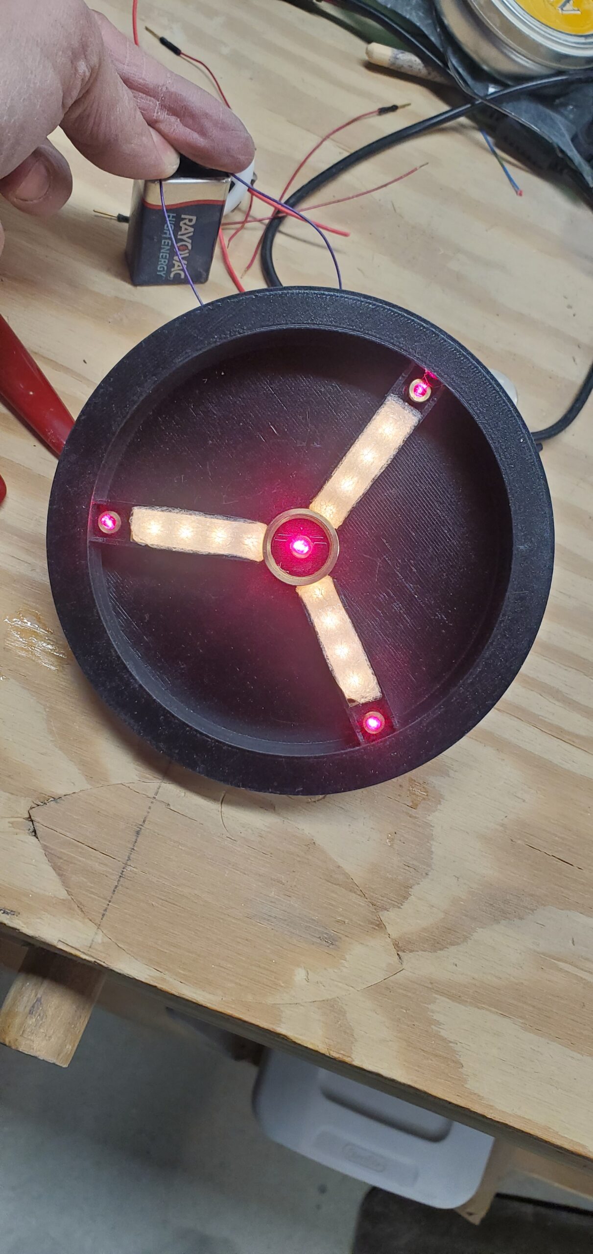
Whether it can actually enable time travel remains unknown. I still have not managed to get the house up to 88 miles per hour.
Lighting the Bulkhead
The overhead bulkhead contains a much simpler light.
A piece of glass forms the visible panel. Privacy film diffuses the surface, while a standard (non-addressable) LED strip surrounds it from behind. Packing foam inside the cavity provides additional diffusion and helps prevent the individual LEDs from appearing as obvious bright spots.
The light does not do anything special. It simply provides a steady glow over the doorway using one of the preset modes on the cheap LED controller. It should probably turn red during an alert.
Then again…not every light needs to perform a complicated sequence.
Most of them, perhaps. But not every one.
A Droid Port That Actually Does Something
The Star Wars-inspired droid port is not merely decorative.
The center section can be removed, revealing the programming cable connected to the Arduino Mega. I can plug a computer into the port and upload new software without dismantling the facade or digging through the electronics compartment.
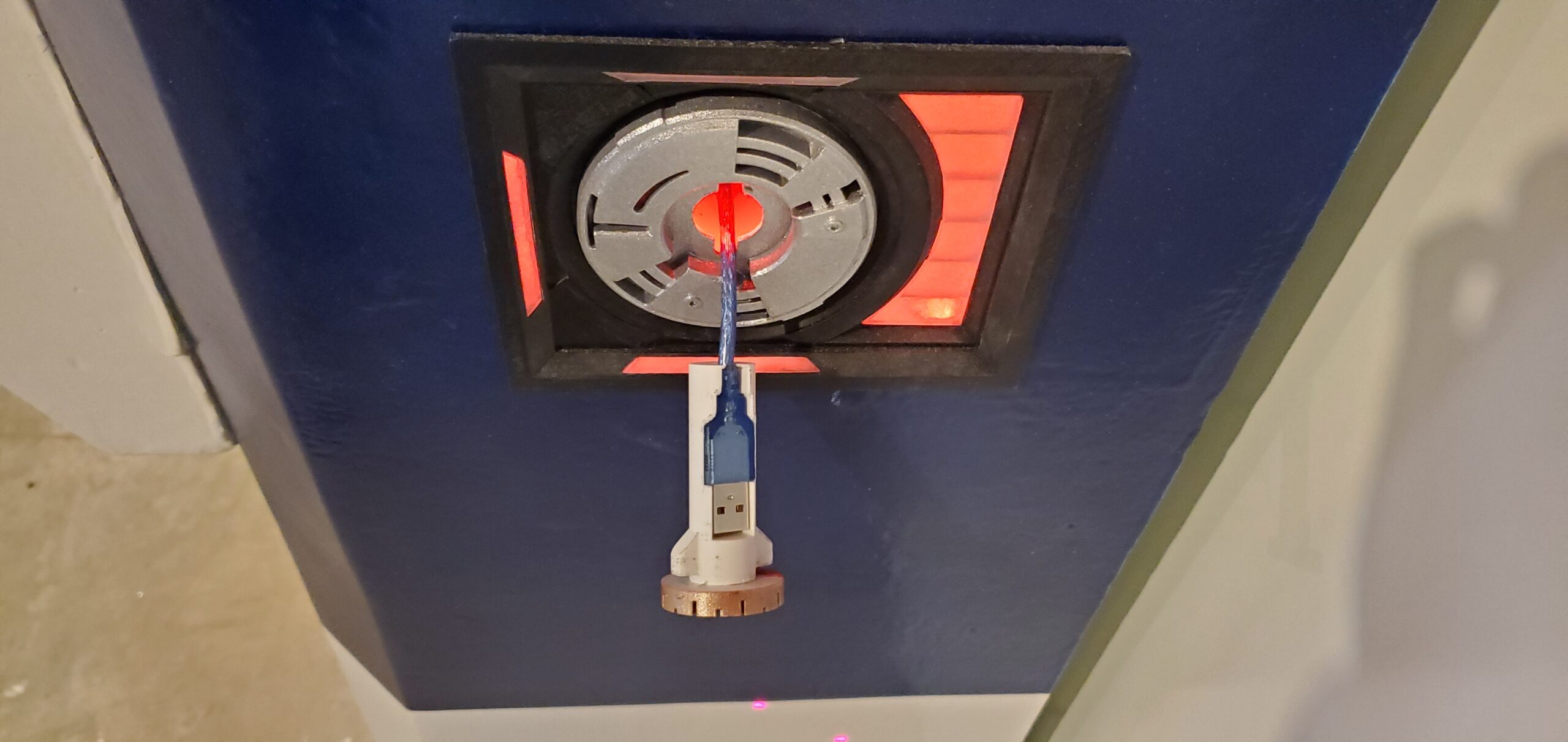
That makes the droid port one of the few science-fiction interfaces in the project with a real-world function closely related to its imaginary one.
No astromech droid is required.
The Airlock Lever
The side of the control-panel assembly includes a large mechanical lever.
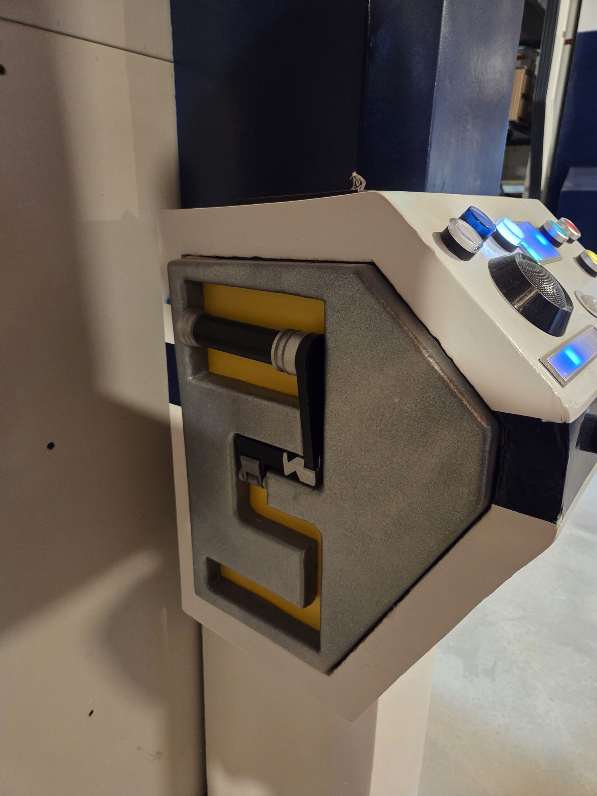
A magnet is embedded in its handle. Reed switches detect when the lever reaches either end of its travel. I originally experimented with Hall-effect sensors, but they did not behave as reliably as I hoped. The simple magnetic reed switches produced a more dependable result.
The Arduino can therefore determine whether the lever is fully open or fully closed.
It cannot yet do anything useful with that information.
I have not committed to the lever’s final function, although muting the sound system is one possibility. For now, the hardware is installed and ready for whatever future behavior seems appropriate.
Sometimes it is important to build an interface before deciding what it controls.
That sounds irresponsible when stated plainly, but it feels perfectly natural on a spaceship.
From Pocket Doors to Automatic Doors
For years, the doors were entirely manual. I opened and closed them by grabbing the ledge inside the window opening and pulling.
Then lightning struck our house during a thunderstorm and destroyed the electronics in our garage-door opener.
This was unfortunate.
It was also a source of parts.
When I replaced the opener, I saved its track, belt, carriage and motor. Those components became the foundation of the airlock’s door mechanism.
I originally hoped to retain the garage-door opener’s control board. The manual up-and-down controls still worked, so I tried to reproduce those signals electronically. I even built a small circuit board to interface with it.
That approach did not work reliably. I no longer remember exactly why, but eventually I abandoned the original controller and operated the mechanism directly.
The motor drives a timing belt arranged in a figure-eight loop. The crossed loop allows a single motor to pull the two door panels in opposite directions: both move outward to open and inward to close.
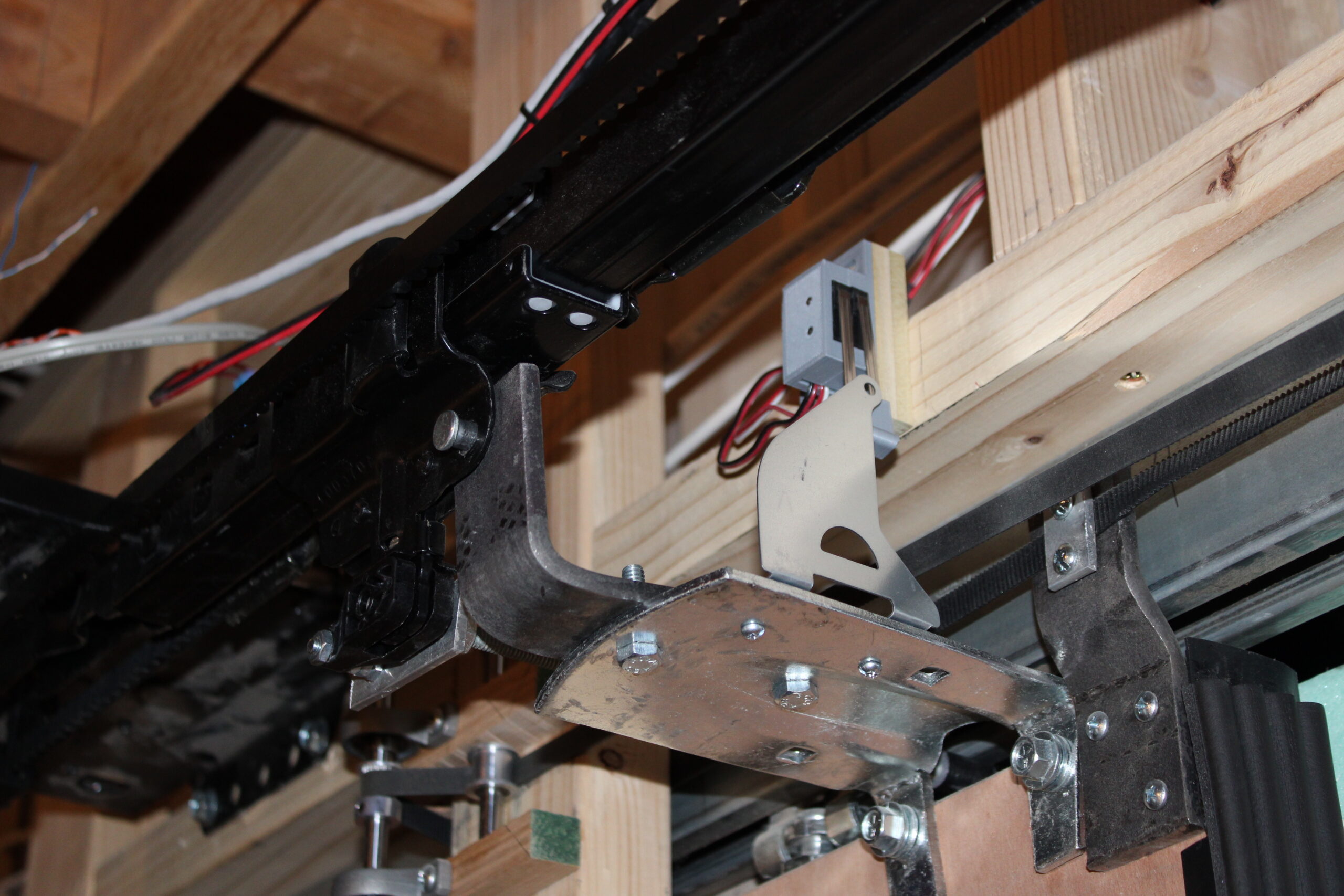
A substantial 12-volt supply powers the motor, so I did not have to worry about starving it for current. The Arduino sends a pulse-width-modulated signal to a DC motor-speed controller, while a relay switches power to the motor supply when the door system is turned on.
This is also the relay circuit that claimed Arduino Mega number two.
One Motor Down
Eventually, the salvaged garage-door motor burned out.
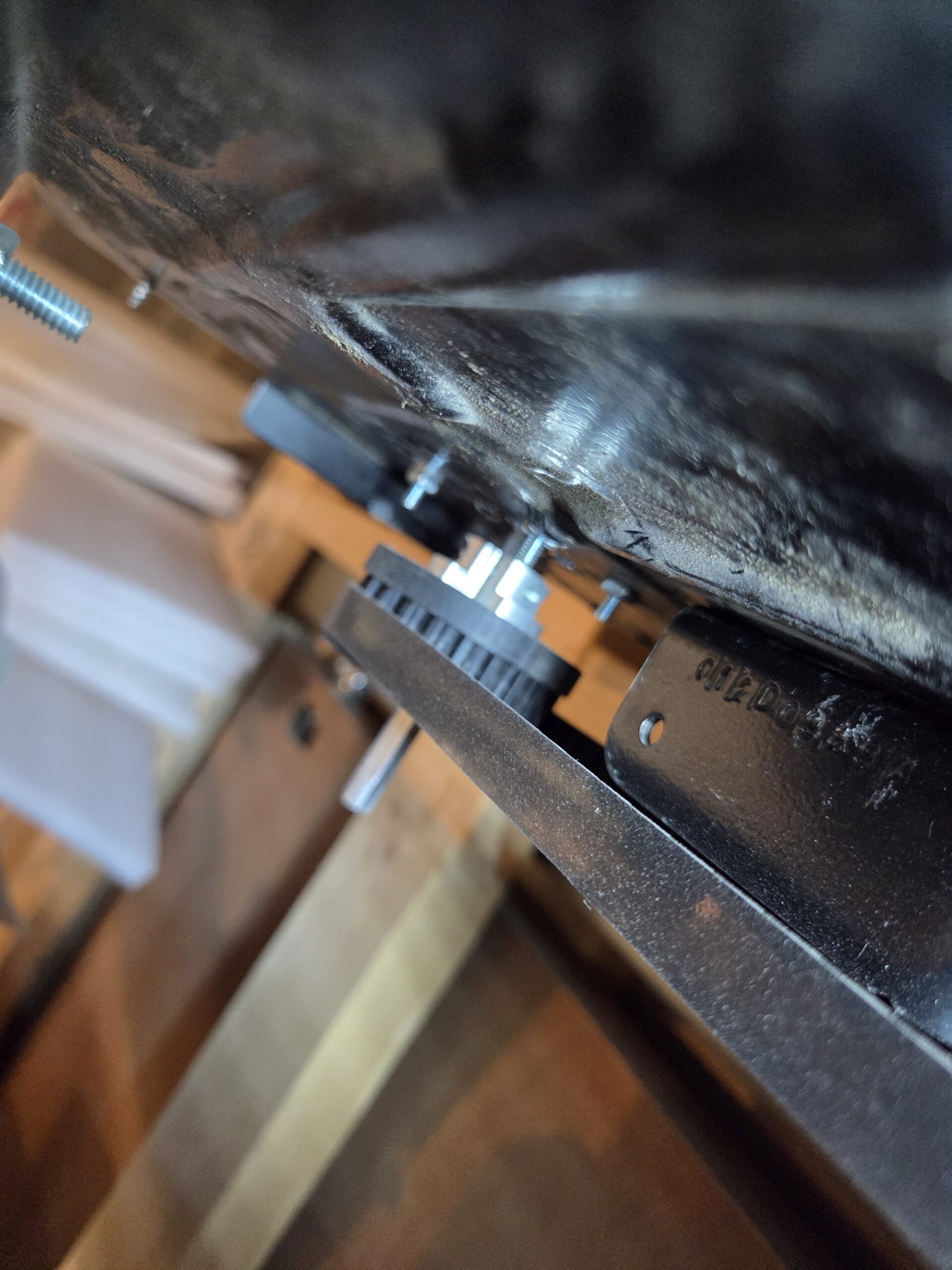
I replaced it with a Yellow Jacket gearmotor from goBILDA. The new motor was slightly faster, which improved the door’s travel speed, but its output did not match the original pulley.
So I designed and 3D printed a custom pulley adapter.
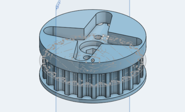
The new part connects the replacement motor to the existing timing belt while preserving the geometry of the mechanism. From the outside, the doors simply began moving a little faster. Behind the wall, the drive system had undergone a small mechanical transplant.
Knowing When to Stop
An automatic door needs to know when it has reached the end of its travel.
More importantly, it needs to stop even if the computer does not notice.
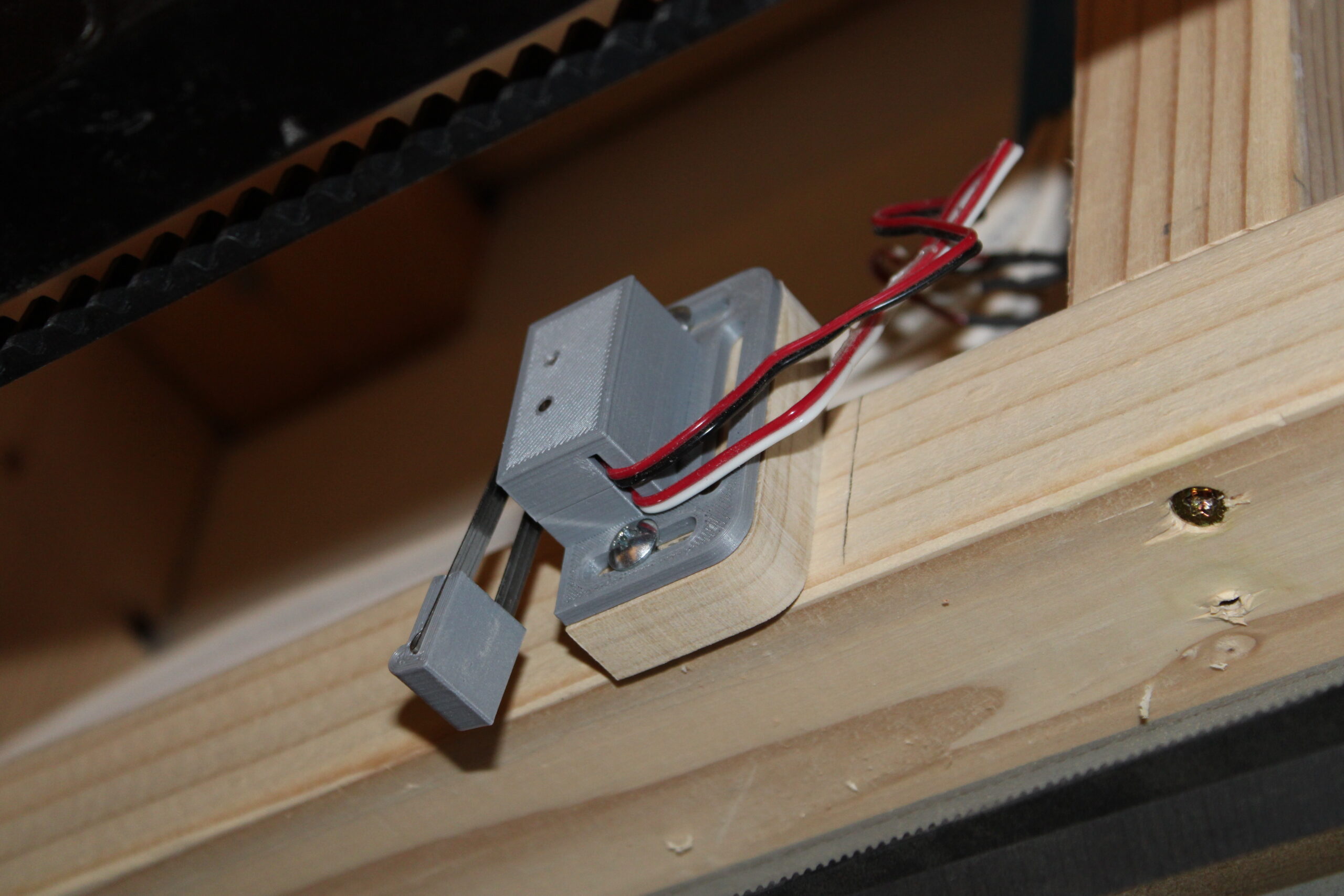
At each end, I installed two limit switches mechanically slaved together inside a custom 3D-printed housing. I could have purchased a double-pole switch, but I already had individual switches.
Also, I am always looking for a reason to 3D print something.
Each switch pair serves two different purposes.
The first switch is normally closed and sits directly in the appropriate motor-control path. When the door reaches the end of travel, that switch opens the electrical connection for movement in that direction. This disconnects the motor independently of the Arduino.
Separate forward and reverse control paths allow the door to move away from an activated endpoint.
The second switch is normally open. When the mechanism reaches the same position, it sends a signal to the Arduino. The software stops its command and triggers the appropriate sound sequence.
The direct electrical cutoff accounts for any delay in detecting or processing the software signal. It also prevents a software failure from continuing to drive the mechanism beyond its intended travel.
The pssshhh sound plays whenever the doors reach fully open, fully closed or stop after a partial movement in Mode B.
This protects the mechanism at its endpoints. It does not provide obstacle detection between the doors. There is no safety edge, optical sensor, current-based obstruction detection or automatic reversal if something blocks the opening.
That is an important limitation – and something I should probably address.
One Button on the Inside
The control panel sits outside the workshop, but I also needed a way to operate the doors from inside.
Rather than duplicate the entire panel, I installed a single button.
If the closed endpoint switch is active, pressing the button opens the doors. If the open endpoint switch is active, pressing it closes them.
If neither endpoint is active, the controller does not know which direction the doors should travel. Instead of guessing, it plays the error sound. Yes. The door chirps at me.
This situation can occur if the doors were stopped partway through their travel using Mode B. Returning them to an endpoint currently requires using the outside controls.
It is not the most sophisticated state-estimation system ever built, but it is appropriately honest about what it knows.
Getting It Right
Looking at the finished system, it would be easy to imagine that the electronics were the hardest part of the project.
They were not.
No individual component was particularly difficult. The challenge was getting all of them right: arranging dozens of LEDs, reading the controls, coordinating the animations, triggering sounds without delays, moving both doors with one motor, detecting the endpoints, supplying enough power and packaging everything behind a removable facade.
It was a collection of manageable problems.
That may be the most accurate description of the entire airlock. I did not begin with every detail resolved. I just kept solving the next problem.
Eventually, the lights blinked. The reactors glowed. The buttons clicked. The doors moved.
And, most importantly, when they stopped, they finally made the pssshhh sound.
Up Next
At this point, we have discussed nearly every part of the airlock except the process that made a collection of blue foam, hardboard, plastic and drywall compound look like a finished structure.
In the final post, we will return to the surface: StyroSpray 1000, sanding, priming, spray paint and the long process of convincing insulation foam that it was actually part of a spacecraft.
Recent Comments