By this point in the project, the outside of the clock made sense.
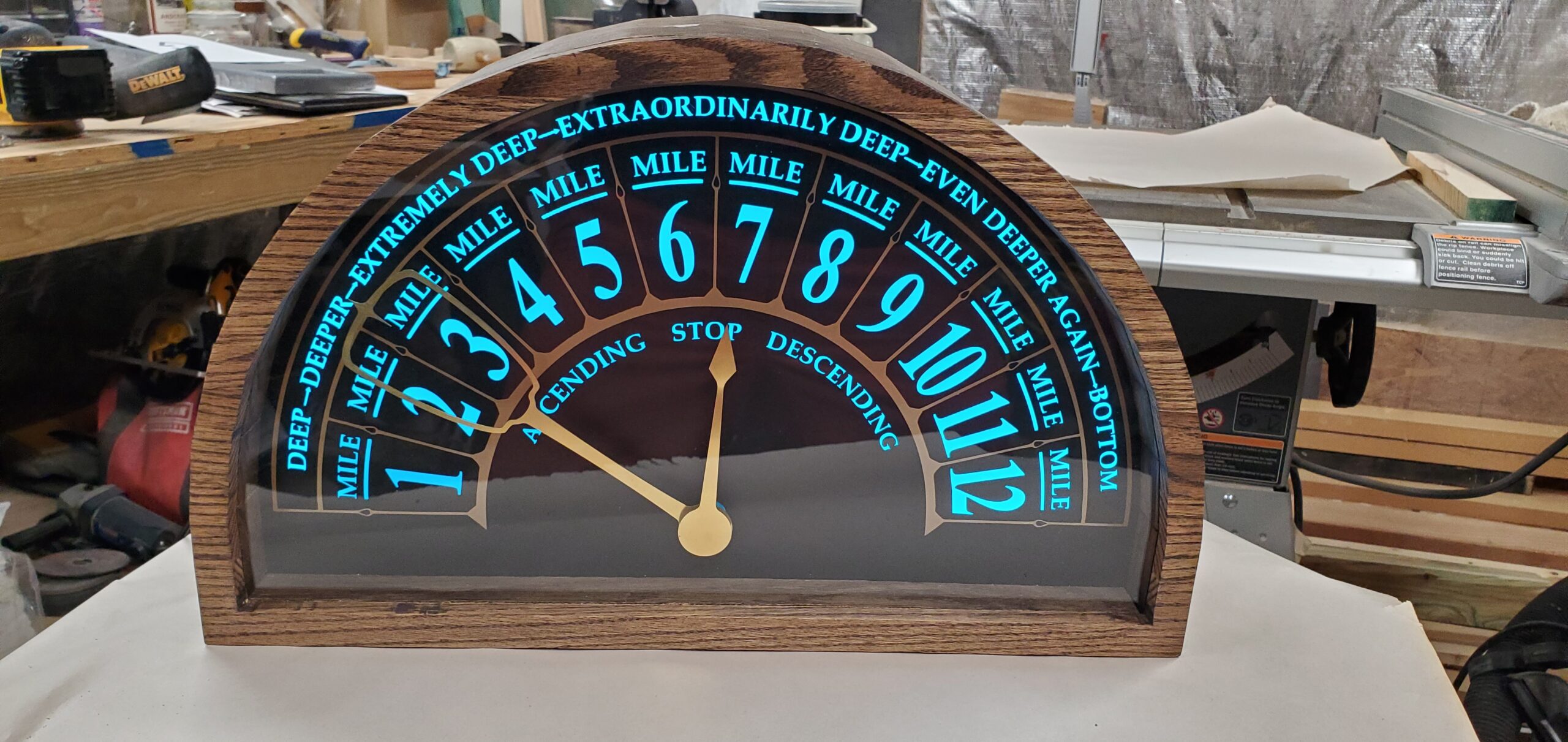
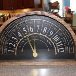
It would look like an old elevator indicator. The face would be a semicircle. The numbers would run from 1 to 12. The hands would sweep across the arc. The lighting would glow from behind the face.
But the part that made the whole idea work was hidden inside.
The clock needed two independently controlled hands moving across the same semicircular scale. One hand needed to point to the current hour. The other needed to show the minutes, using the same 1-through-12 layout as a traditional analog clock.
That sounds simple when you describe it from the front.
It is much less simple when you try to build it.
Why a Normal Clock Movement Would not Work
A standard clock movement is designed for a round clock face.
The hour, minute, and sometimes second hands are stacked on concentric shafts. Each hand rotates around the same center point. The mechanism handles the different speeds internally: the hour hand moves slowly, the minute hand moves once around every hour, and everything is built around continuous circular motion.
That is perfect for a normal clock.
This clock was not normal.
The face was a semicircle, not a circle. The hands did not need to rotate continuously around a full 360 degrees. They needed to sweep across an arc, more like an instrument gauge or an elevator floor indicator.
The hour hand needed to move to the correct hour and stay there. The minute hand needed to travel across the same scale over the course of each hour.
That meant I needed independent control over each hand.
So instead of using a clock movement, I used servos.
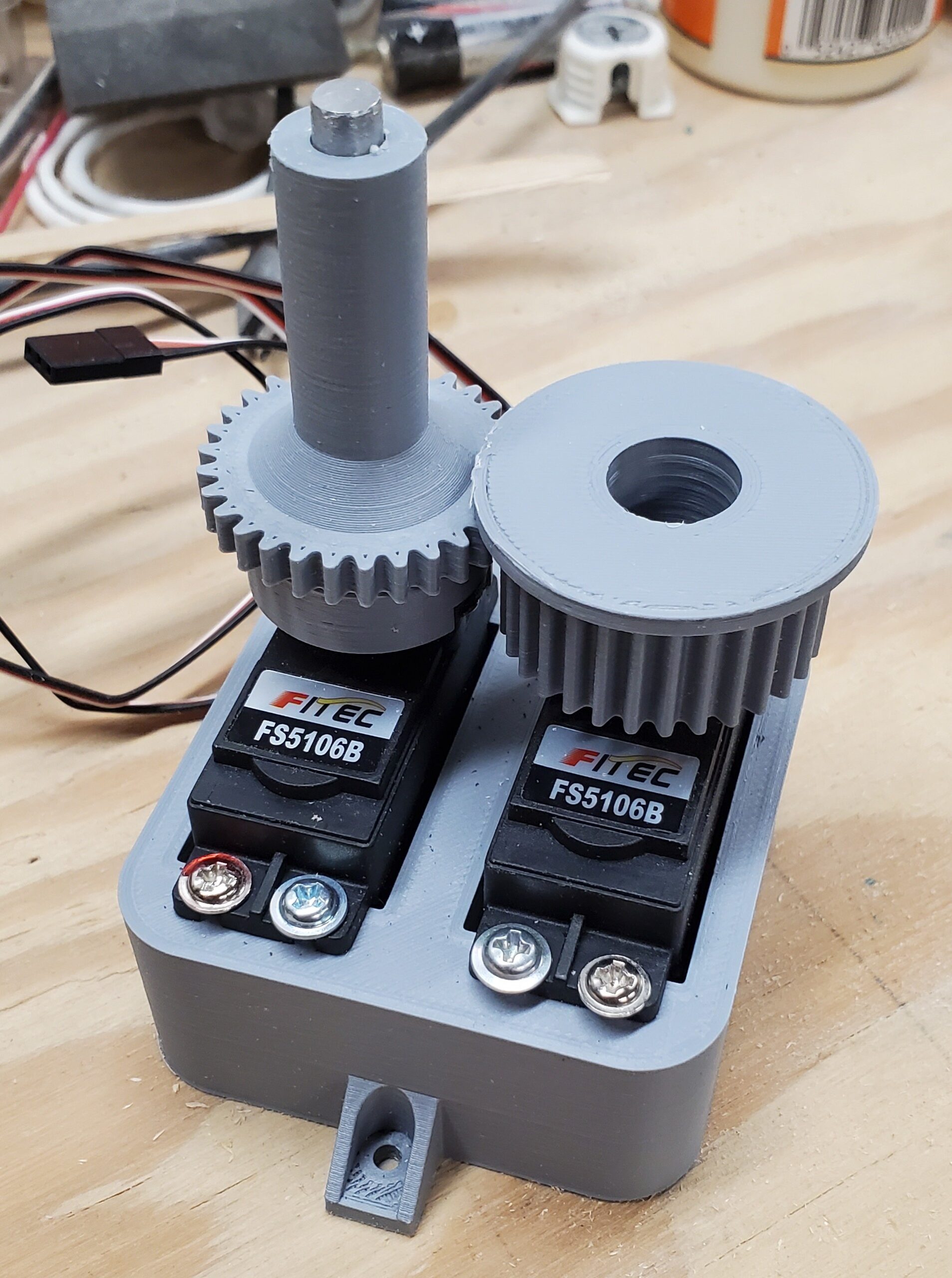
Two Servos, Two Hands
The design uses two servos: one for the hour hand and one for the minute hand.
The hour hand is the simpler of the two. It is direct drive. The servo rotates to the angle that corresponds to the current hour, and the hand points to the correct number on the face.
The minute hand is where the mechanism gets interesting.
The minute hand also needs to sweep across the same arc, but it cannot simply attach to the same shaft as the hour hand. The two hands need to move independently, and the minute hand needs to move around the hour-hand shaft without interfering with it.
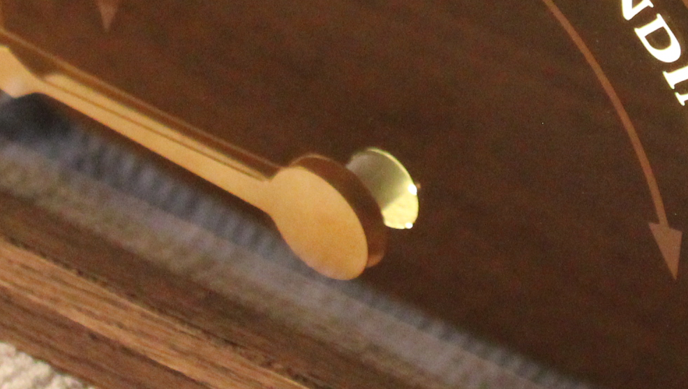
The solution was to drive the minute hand with a gear that slips around the hour-hand shaft.
That one design choice became the heart of the mechanism.
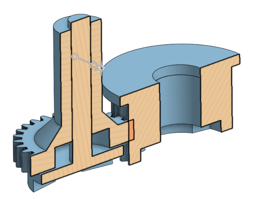
The Slipping Gear Idea
The easiest way to understand the mechanism is to separate the two jobs.
The hour hand needs a shaft.
The minute hand needs to move as if it shares the same visual center, but it cannot be locked to the hour-hand shaft.
So the minute-hand drive gear is arranged so it can move around that central shaft. The hour-hand shaft passes through the mechanism, while the minute-hand gear drives the second hand independently.
From the viewer’s perspective, the hands belong together. They are part of the same clock face, pointing across the same set of numbers.
Inside the case, though, they are two separate mechanical systems coordinated by software.
That separation was the key. Once I stopped thinking of it as a normal clock movement and started thinking of it as two independently positioned indicators, the problem became much more solvable.
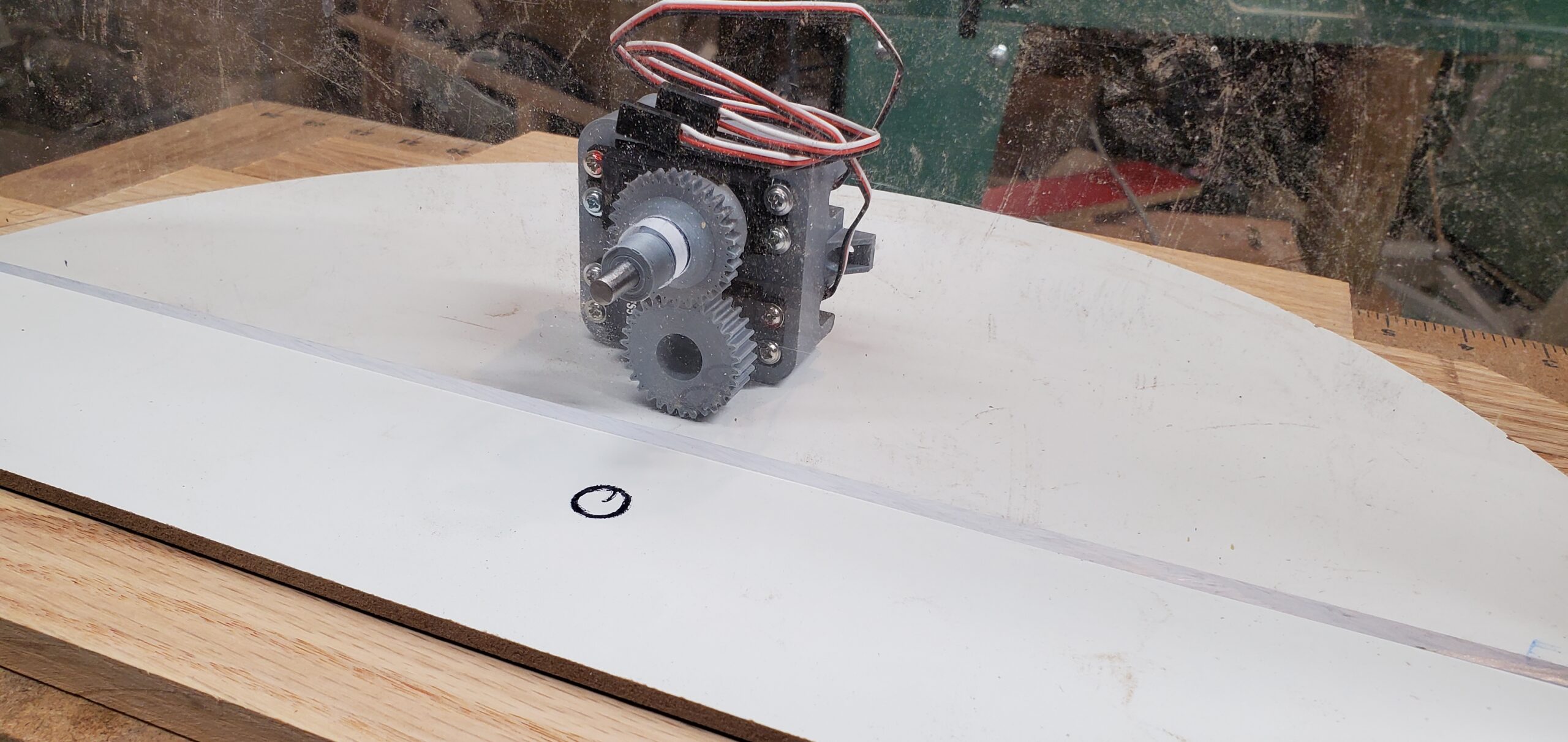
Designing the parts
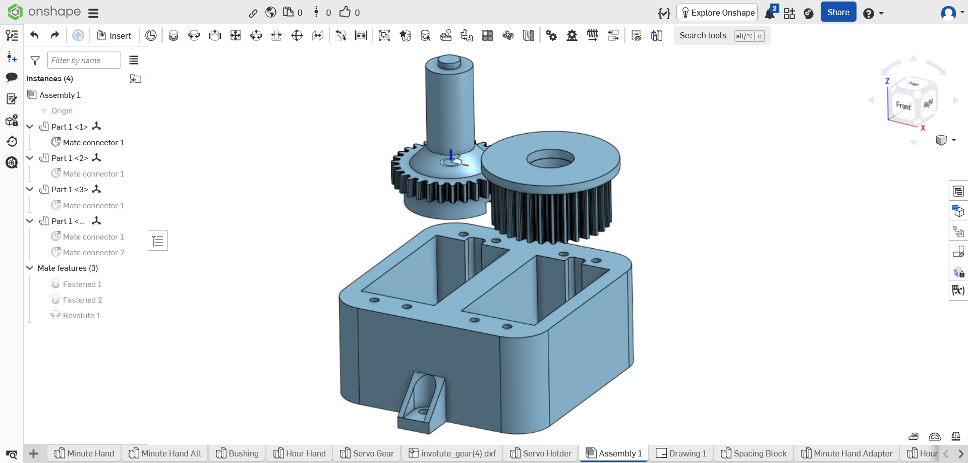
I designed the mechanism from scratch in OnShape.
That was one of the fun parts of the project. The mechanism was not something I could buy off the shelf, and I could not find a clock like this already on the market. The geometry had to be worked out specifically for this case, this face, and this hand arrangement.
Once the parts were designed, I printed them on a Creality Ender 3.
3D printing was a good fit because the mechanism needed custom geometry, but it did not need to be decorative. Most of the printed parts would be hidden inside the clock. They needed to be accurate enough, strong enough, and adjustable enough to get the hands moving correctly.
This is one of the places where modern maker tools are incredibly useful. A project like this would have been much harder if every custom part had to be cut, machined, or fabricated by hand. With CAD and a 3D printer, I could design around the exact problem and iterate until the mechanism worked.
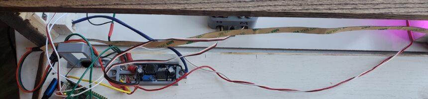
The Electronics
The original Christmas parts included an Arduino, and that was the initial direction for the project.
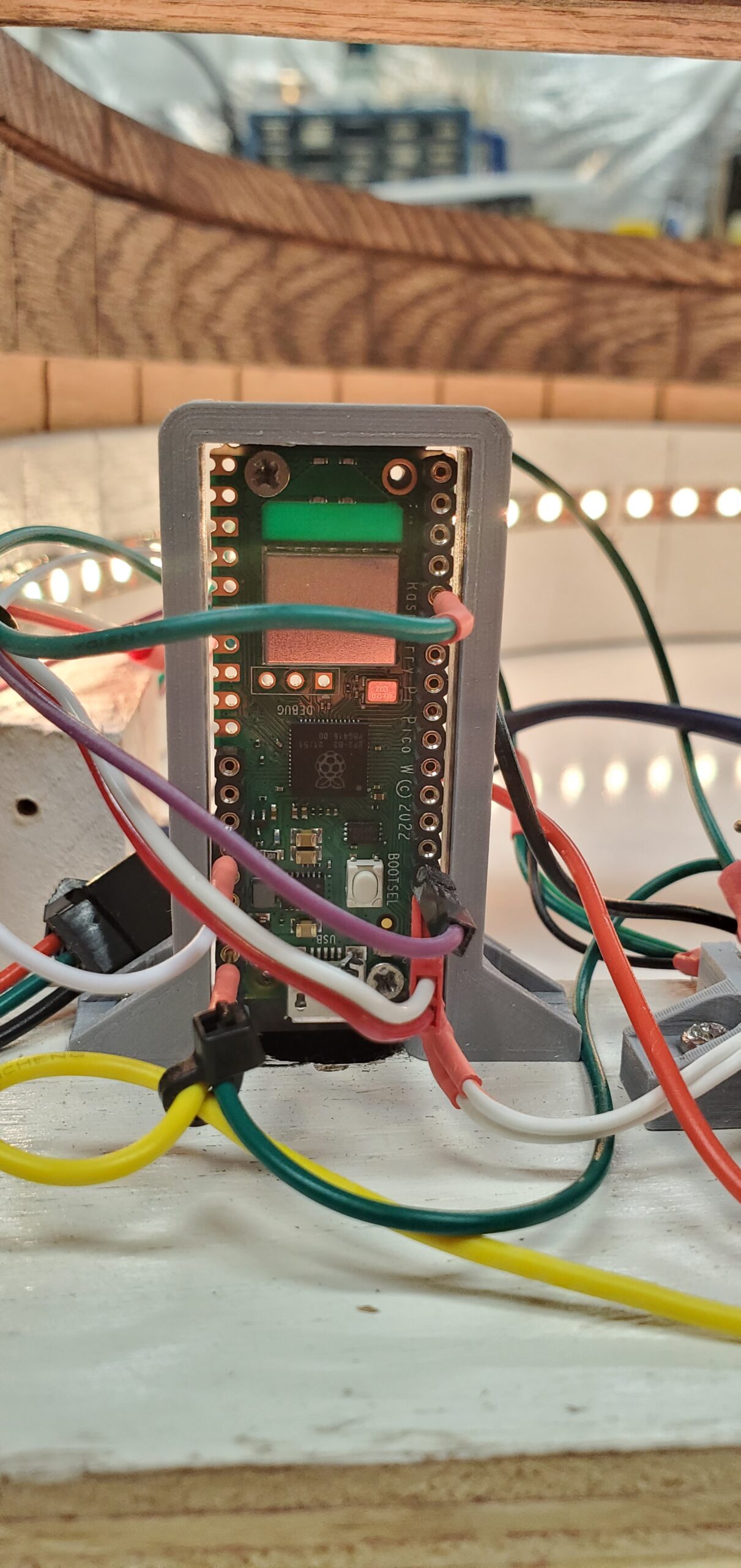
Eventually, I replaced it with a Raspberry Pi Pico W.
The Pico W made sense because it could connect to the internet and get the current time. Once it had the time, it could keep time locally and move the servos to the correct positions. It also made it easier to sync with Daylight Savings Time.
The Pico W ended up handling several jobs:
- connecting to the internet to get the current time
- keeping track of time after synchronization
- moving the hour and minute servos
- controlling the LED backlighting
- reading the button for light modes
- reading the switch that turns the lights off
That gave the clock a little more intelligence than a standard movement. It did not need to be manually set in the same way, and the lighting could be controlled as part of the same system.
Mapping Time to Motion
Once the electronics and mechanism were in place, the software problem was conceptually straightforward: convert the current time into servo positions.
The hour hand points to the current hour.
The minute hand moves across the 1–12 scale just like the minute hand on a traditional analog clock. At the top of the hour, it points to 12. At 15 minutes past, it points near 3. At 30 minutes past, it points near 6. At 45 minutes past, it points near 9.
Because the face is a semicircle, the software does not map time to a full 360-degree rotation. Instead, each hand moves within the usable arc of the clock face.
That is one of the nice things about using servos instead of a traditional movement. The software can define the relationship between time and position. The physical face does not have to follow the assumptions built into a normal clock mechanism.
The Lighting Controls
The LEDs are decorative backlighting, but I still wanted some control over them.
The clock has a button to change between the different LED modes. It also has a switch that acts as an override to turn the lights off.
That gave the clock a little flexibility. The backlight could be part of the visual effect when wanted, but it did not have to be on all the time. You can even control the LEDs on a schedule.
The LEDs are placed around the side of the arc and along the bottom of the clock, behind the face. A layer of cellular foam diffuses the light so the face glows more evenly instead of showing bright points from individual LEDs.
The lighting is not mechanically necessary, but it matters to the feel of the finished piece. Without it, the clock would still work. With it, the clock feels much closer to the object I had in mind.
The Problem that Took an Hour to Appear
Not every problem showed up right away.
At one point, the servos would work for a while and then stop after about an hour. They would just twitch.
That kind of bug is especially annoying because it does not fail immediately. The clock could look fine during a quick test, then quietly stop later. It took a different kind of troubleshooting because the problem was not just “does this work?” It was “does this keep working?”
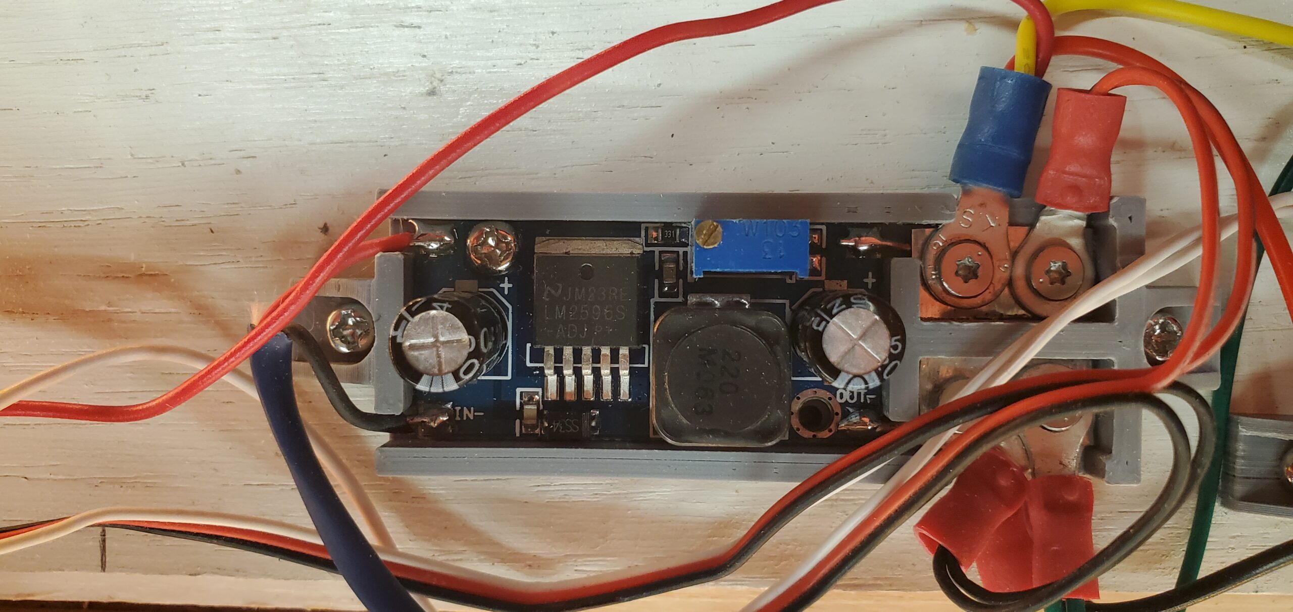
The issue turned out to be the power supply overheating. As the power supply warmed, it stopped delivering sufficient current. I contemplated drilling holes in the top to vent the heat, but that would ruin the finish…and I would have to deal with errant light escaping through those holes.
The fix was to eliminate that supply and power the device directly with the voltage it needed.
After that, the clock could keep running.
The Moment that Mattered
There were plenty of satisfying technical moments in the project.
The first time the mechanism moved correctly was exciting. The first time the Pico W synchronized time and moved the hands into position was exciting. The first time the lights glowed through the face the way I hoped was exciting.
But none of those were the real “it works” moment.
The real moment was when Annabelle saw the clock finished.
That was when the whole project became what it was supposed to be.
The mechanism mattered. The software mattered. The woodworking mattered. The electronics mattered. But they all existed to support one thing: turning a promise into a real object.
When she saw it, nothing else mattered.
Next: Building the Body
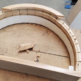
With the mechanism working, the next challenge was making the clock look like it belonged outside of a prototype.
That meant building the case, shaping the curved body, cutting the face, applying the vinyl, fitting the LEDs, and making the front trim.
It also meant learning that small curved pieces and planers do not always get along.
That is where the project moved from mechanism to woodworking — and where one part of the clock exploded inside my planer.
Recent Comments